Close

Questions involving levers require the candidate to identify the correct position in which a force must be applied in order to establish the equilibrium between two parts of levers which have opposite tendencies of rotation. In addition, they require one to figure out the missing force at one side of the system to set the equilibrium, if the distances from the turning point are given.
Another important point of this module is working out the resultant turning effect (moment) of force if the equilibrium cannot be established. The situation can be more complex if the weight of the lever is also included in the calculations.
In the test, it is very important to approach questions with some urgency as time is extremely limited. One should take care not to linger too long on any single question as it takes up valuable time which would be better-allocated on other, more approachable questions. While this guide will explore the means by which to approach the questions regarding levers, it is vital that if you cannot identify a path to a solution within 10-12 seconds you take an educated guess and move on to the next question. Spending too much time on any single question can cost precious time which is better spent elsewhere on less challenging problems.
First, let’s have a quick view on levers, before entering into details, which will be discussed when the types of levers are explained.
Levers are one of the simplest types of simple machines. As such, they possess the main properties of simple machines, i.e.:
Levers consist on a rigid bar which can turn around a fixed point. This turning point is known as pivot or fulcrum.
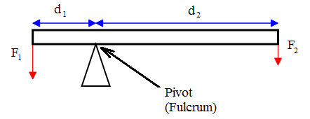
The turning point divides the system into 2 main parts:
Thus, the equilibrium is settled when the turning effects (moments) caused by the two forces applied at the given distances from the turning point, cancel each other. In simplest words, the condition of equilibrium in this case is
Total clockwise moment of force=Total anticlockwise moment of force
1.2 Equation of levers
The mathematical equation of the abovementioned rule is
![]()
where
F1⊥ and F2⊥ are the components of acting forces on both sides of the bar which are perpendicular to the bar length, while d1 and d2 are the distances of the points where the forces act to the fulcrum.
In general, a lever is used to lift a load L using a force F. Therefore, instead of writing F1, F2, d1 and d2, we can write L for F1, dL for d1, F for F2 and dL for d2.
Hence, the equation of levers becomes
L×dL=F×dF
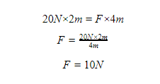
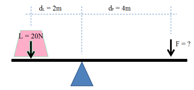
For example, if the load in the figure below is 20N and the distance of the center of gravity of the load from the turning point is 2 m, the magnitude of force F will be
1.3 Mechanical advantage
Another important quantity regarding levers is Mechanical Advantage (MA). It is calculated by the equation
![]()
It calculates how many times easier we can lift a load using the lever than if we simply lifted it by arms.
In our example, the mechanical advantage is
![]()
This means we can lift the load 2 times easier when using the lever instead of carrying it by hand.
1.4 Types of levers
We determine the class of the lever by noting the relative positions of the load (L), pivot (P) and force (F).
The three possible combinations are:
Each of these combinations gives a different class of levers.
1.4.1 First class levers
A first class lever is used to lift heavy loads with small forces. It has a fulcrum between the force and the load as in the figure of the previous example
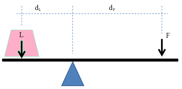
If the system is in equilibrium there are two equal turning effects but in opposite directions. According to the law of levers we can write
![]()
The force applied to the lever can also be calculated from the law of conservation of energy. Look at the figure below:
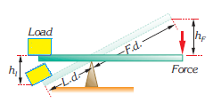
Giving that
Work done on the load=Work done by the force
we obtain
![]()
From the similarity of triangles, we obtain
![]()
where k is a constant. Hence, we obtain

Substituting the last expression in the equation (1), we obtain
![]()
Simplifying k, we obtain
![]()
which is identical with the equation (2).
1.4.1.1 Examples of first class levers in daily life
There are many examples in daily life when the principles of first class levers are applied. Scissors, see-saws, can openers, equal-arm balances and crowbars are all examples of first class levers.

Scissors (first class lever)
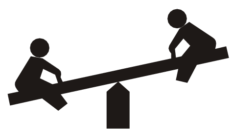
Seesaw (first class lever)

Seesaw (first class lever)

Equal-arm balance (first class lever)
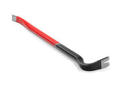
Crowbar (first class lever)
Example: Calculate the force needed to pull out a nail using a crowbar as in the figure. The nail can take a maximum force of 2000 N.
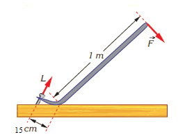
Solution: Crowbar is a first class lever, so, its fulcrum is As we see, the distance from the load to the turning point (dL) is 15cm = 0.15m and the distance from the force to the turning point (dF) is 1m. The maximum force the nail can take (2000 N) here represents the load L. Thus, for the force F needed to pull out the nail, we have

The mechanical advantage of this crowbar is
![]()
The same result can be obtained also by dividing the distance from the turning point. Thus, from the equation
![]()
we can write
![]()
As you can see, the result is the same in both cases.
1.4.2 Second class levers
A second class lever has the load between the force and the fulcrum as shown in the figure below

The equation of a second class lever is the same as for the first class lever, i.e.
![]()
And the equation of mechanical advantage is also the same:
![]()
The only difference here is that in most cases, force distance is equal to the total length of the lever.
Wheelbarrow, nutcracker and bottle opener are all examples of second class levers. Look at the figures below

Wheelbarrow (second class lever)

Nutcracker (second class lever)

Bottle opener (second class lever)
Example: A man carries a 600N load using a wheelbarrow. What is the force the man applies for the values given in the figure? Find the mechanical advantage of the wheelbarrow? Ignore the weight of wheelbarrow.
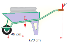
Solution: From the figure we can see that dL = 40cm = 0.4 m, dF = 120cm = 1.2m and L = 600N. Thus, using the levers equation
![]()
we can work out the force F.

The mechanical advantage of this wheelbarrow is
![]()
1.4.3 Third class levers
A third class lever has the force between the load and the fulcrum, as shown in the figure below

A third class lever also obeys the law of the lever
![]()
Sugar tongs, tweezers, forearm etc. are good examples of third class levers.

Sugar tongs and tweezers (third class lever)

Forearm (third class lever)
Example: Calculate the force needed to catch a 20g ball using the tweezers as in the figure above if the length of tweezers is 9 cm and the force is exerted at a point 6 cm from the turning point. What can you say about mechanical advantage of these tweezers? (Take the approximate value of 10 m/s2 for gravity in this example).
Solution: first, we have to work out the load L which is equivalent to the weight W. Giving that mass m = 20g = 0.02 kg, we obtain
![]()
Now, using the equation of levers
![]()
Substituting the values dL = dtotal = 9cm = 0.09m and dF = 6cm = 0.06m, we obtain

The mechanical advantage is
![]()
In this case the mechanical advantage is less than 1. This means the force needed to lift the load is greater than the load itself. For this reason, one may think this type of lever is useless as we have to use a greater force than needed to lift the load. However, third class levers are usually used to lift light objects. Thus, the force is also small.
The usefulness of third class levers consist on the fact that they are used when no other options are available. Ethics is also a reason why we use third class levers. It is not ethical
catching the sugar lumps with fingers. On the other hand, you cannot use the hands to move a burning wooden block but you would use tongs for this.
Important note: In all the above examples, the weight of levers was not mentioned. It is either very small to be taken in consideration, or it was taken together with the load.
1.5 Finding the correct approach on the questions involving levers
The diagram below represents a guide on how to approach the questions about levers.

1.6 Summary
Levers are one of the simplest types of simple machines. As such, they possess the main properties of simple machines, i.e.:
The equilibrium is established when the turning effects (moments) caused by the two forces applied at the given distances from the turning point, cancel each other. In simplest words, the condition of equilibrium in this case is
Total clockwise moment of force=Total anticlockwise moment of force
In symbols,
![]()
where
L is the load in Newtons,
F is the force in Newtons,
dL is the distance from the load to the fulcrum, and
dFis the distance from the force to the turning point.
The above equation is known as the equation of levers.
We determine the class of the lever by noting the relative positions of the load (L), pivot (P) and force (F).
The three possible combinations are:
Mechanical advantage is an important quantity that shows how easily one can lift a load using the lever rather than carrying it by hand. It is calculated by the equation![]()
In first and second class levers, mechanical advantage is greater than 1, while in the third class levers mechanical advantage is less than 1. This means that in third class levers we have to use a greater force than the load. However, they are very useful in certain situations.